- Home >
- Equipment
Test Equipment and Code
Testing and Infrastructure Hardware Provided by Generous Donations from:
 |
 |
 |
 |
Starting Out
For the inital set of testing, we made due with the things to which we already had access. HobbyKing.com donated a thrust test stand, which got us started. A friend donated an Eagle Tree v2 data logger with an electrical RPM sensor. Unfortunately we initially had no way of logging thrust directly to the data logger. By the combination of thrust data collected on the stand at fixed throttle points, we combined the collected RPMs with the thrust data to generate a non-linear regression analysis for HQ 5x4 propeller used in the initial tests. Because of the correlation between RPMs and thrust for a given prop, the formula based on the regression analysis should hold for each prop regardless of the rest of the power train. We also created a PWM generating program for the Arduino Uno that output a consistent test program, ensuring the throttle passes were identical in each test. Also, we set all ESCs that supported BLHeli to use the same revisions and same settings. As we tested KISS ESCs as well, that was the one exception. Since we tested with damped light enabled, we couldn't use a bench supply to power the test. Instead we used an 1800mah 65C 4S Dinogy battery in the first test. To account for small differences in battery voltage, we derived a rating system for the ESCs that divides the maximum thrust by the measured battery voltage at the beginning of the test. By using a consistent setup we attempted to isolate as many variables as possible, leaving the ESC as the only variable in the test. The PWM generation code used in the first test is available here.
Evolving Methodology and Equipment
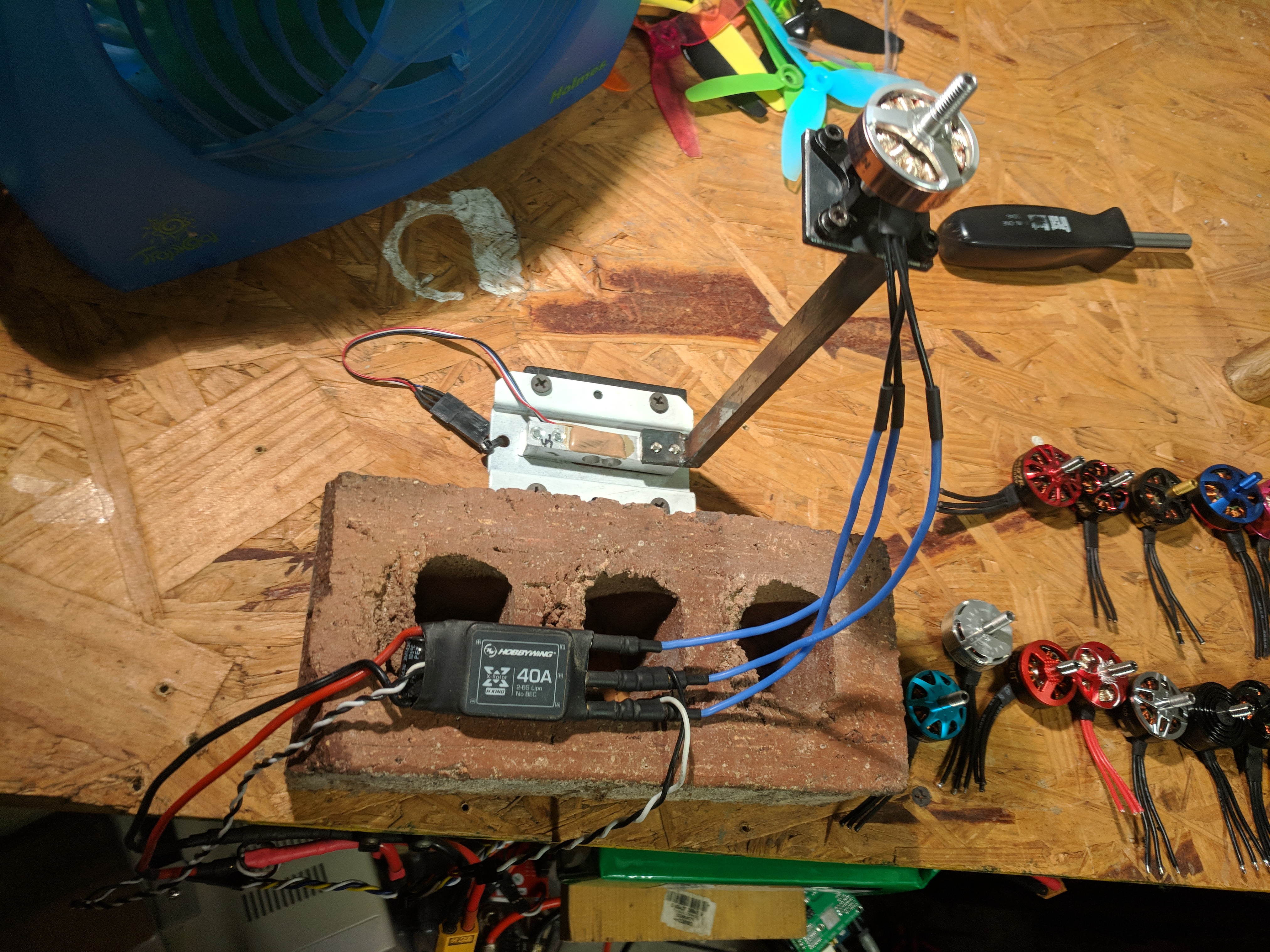
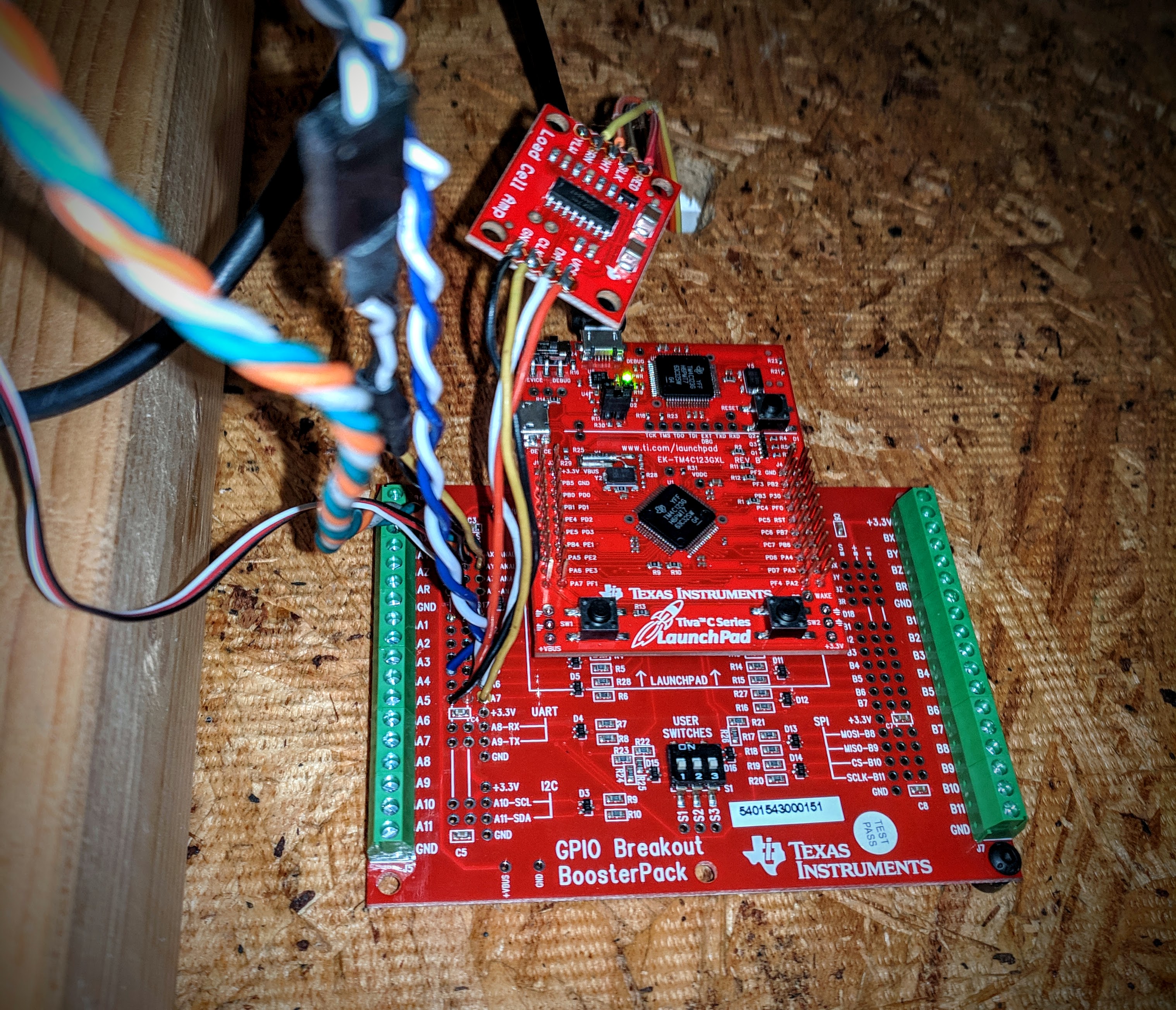
After seeing the weaknesses in the first setup and looking through our parts bin, we quickly decided to develop a testing platform that would be more accurate, higher resolution, and above all easily repeatable and inexpensive. Since we already had the Turnigy thrust stand we decided to use the existing platform as a basis for the new equipment. Based on suggestions on RCGroups, and a very helpful blog post, we purchased and adapted a HX711 load cell amplifier for use with the load cell in the Turnigy stand. After some significant adaptation of the code provided by the Davis Rotorcross blog, optimizing the analog read code for oversampling and simultaneous reads, and tweaking the loop and pwm generation sequences we developed a workable solution for our second set of tests. The software is currently targeted to run on the TivaC Launchpad development platform from Texas Instruments, outputting the throttle pulses using the available hardware PWM perriferal and collecting sensor data via the 12-bit ADC with hardware oversampling. Originally, a Team Black Sheep 100A current sensor was used along with a voltage divider to log voltage and current, though a new sensor has recently been added (See Below). An inexpensive latched magnetic hall effect sensor was also used to detect RPMs at the motor, though the electrical RPM sensor used in the first test also works with the new code. After some exploration, the latched hall effect sensor only works on motors larger than 2206, as the magnets below 2208 don't seem to be strong enough to trigger the sensor. Fortunately the EagleTree electrical RPM sensor is working well, though any pulse-based RPM sensor will work with the code. The data from the load cell is also logged at 80hz. The code for test is available here, though it is still being actively updated and is rapidly evolving, so it may be out of date or even broken at any point depending on where I am in development. I'll try to get a stable version uploaded soon and move my modifications to a new branch, but I haven't had a lot of time to work on coding recently.
Moving Forward: Challenges and the Future
 I had so much trouble with reliability on my previous thrust setup that I made some revisions for the recent tests. I abandoned any mechanical transfer setup, and direct mounted the motor to a new load cell. This setup is repeatable to the gram. Thrust numbers are now MUCH more reliable and extremely accurate. I was very pleased by the new setup in this test. The prop has 100mm clearance from load cell plate, and is pushing down against the load cell, not pulling. Based on my testing this has zero impact compared to a free flowing prop in the 4-6" range, which is all I am testing. Compared against the free air flow stand the numbers were within the margin of error.
As mentioned I also modified the code to use the TivaC hardware PWM driver. I am able to generate an accurate oneshot125 (125us to 250us) signal from 500hz to 3.8khz refresh rates. I found that many ESCs had issues with 3.8khz, especially on the higher KV motors (see the 2700kv 2205 ESC test run for more information on that), so in the end I backed the refresh rate down to 1khz, which seems to be the best comprimise between latency to the ESC and compatibility with the slower MCUs.
I also replaced my shunt resistor based current sensor with a hall effect bi-directional sensor. I was having some odd issues periodically with the shunt resistor current sensor. Noise on the power lines really had an effect on the readings and if an ESC blew or lost sync it would dump current into the analog pin and burn out the analog sensor for that pin in the MCU. --OZ-- from RCGroups sent me a ACS758ECB-200B 200A bi-directional hall effect current sensor, and I finally got it hooked up. Even though it's a theoretical loss of resolution with the 400A range vs the 100A range, the new sensor is much more sensitive and responsive and getting better readings. Interestingly enough the bidirectional sensor is useful as it actually shows negative amps during times when the braking is kicking in, which is pretty wild to see. It showed over 4 amps in reverse during some parts of the run. It's also catching the high current peaks better too. As a bonus it's not electrically connected so it doesn't induce noise and won't blow my analog pin. See the graph below for the run on the bi-directional sensor.
Also moving forward I would like to add an optical RPM sensor to detect physical RPM changes in additon to electrical. I have the sensors on hand, but need to wire the hardware and ensure that the code works correctly with the new sensor. Keep track of the code I use for testing on my GitHub Repo. I'll try to keep it up to date as I make changes.
Maintenence Updates
 After several years of using this hardware regularly, the long term durabilty and accuracy of this setup has been excellent. In mid 2018 we went through the process of replicating the stand for a second testing site and have made some slight updates to the code. In addition I've added an I/O breakout booster pack to the TivaC that allows for cleaner signal and some added input protection on the signal lines. This should help protect the main TivaC Launchpad from upstream electrical spikes that are fairly common on these high powered brushless systems.
In addition to the main circuit the power supply has been updated. There were some issues with the short circuit protection triggering on high transient loads on the Venom powersuppies we initially used. As a result we updated to current limited supplies, a Volteq HY3080EX 0-30V variable 80A maximum supply for high voltage (5S-6S) testing, and a TekPower TP3050E 0-30V variable 50A maximum supply for the 4S tests. Both have been working very well with the addition of a high capacity battery in line parallel to handle any current spikes during transitions that the supply can't provide. This has proved to be a very robust and accurate setup, definitely decreasing our margin of error on the voltage supply side.
Overall I think the system has matured well and has been remarkably stable. It remains very inexpensive to set up, with the exception of the power supplies (big thanks to T-Motor and Catalyst Machineworks for funding for our second high voltage unit). If you're looking ot replicate our setup, less expensive solutions are available, such as simply powering from a large capacity battery, though that impacts repeatability and accuracty to a certain extent. Our goal is to make this setup as easy to replicate as possible. We'd love to see more community data available as others verify and expand on our tests.


