The Truth About Custom Motor Mixes

The option for custom motor mixes in flight controller software has been around for a tremendously long time, since the early days of MultiWii, long before the current 32-bit revolution took over the flight controller market. There's a ton of information and theories out there, from old wive's tales, to handy web calculators to help an enterprising pilot with this feature, but what is the truth? Is it even necessary?
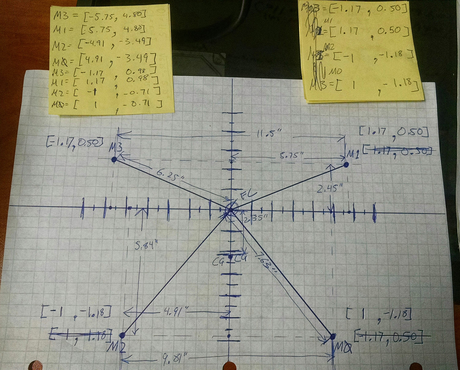
Back in my early days of multirotor adventuring, I happened to snag a really good deal on an ImmersionRC XuGong 8" quad. Thanks to the asymmetrical "dead cat" layout of the frame I launched a bunch of research into the details of custom motor mixes, doing a bunch of math, and talking to some really smart people along the way to figure out some things that didn't really add up to me about the application of this theory on a flat layout asymmetrical frame. There are tons of theories about how and why to calculate a custom motor mix, and I think it is worth looking at the process I took exploring this, as it is still a discussion I see happening around the multirotor community.
Theories of Calculation
First let's identify the primary theories involved here as to how and why to calculate custom motor mixes on a flat frame (where all 4 motors are pointed down by possibly in an asymmetrical arrangement). There are really two main competing theories in the discussion, and the polar opposites of these theories are what clued me in to this research in the first place.
The first theory is that as motors change distance from the center of rotation, the distance a motor needs to travel per degree of rotation increases as the radius increases. We can address this fairly easily mathematically by the relationship between R and the circumference of the circle, giving us the relationship between R and the distance travelled as (2 * pi * r) / 360, reduced to (pi * r) / 180, or r / 57.296, or simply rounded to 0.01745 * radius, which is more than sufficiently accurate enough for our concept here. What we really care about here is that it is a proportional relationship between radius from the center of rotation and the change in distance required per degree of rotation. That means we can basically calculate a simple ratio between arm lengths where our PID controller gains are increased as the distance of the point of applied force (the motor) gets further from the center of rotation. This is probably the most common theory behind the calculation of custom motor mixes, and the one we typically see used in those web based calculators floating around. It all sounds great up to this point. Sound physics and math, correct? BUT... There's more.. A lot more!
Since I had taken university statics and dynamics recently enough back when I was playing with the XuGong to still have some recollection of what I learned, my immediate thought was to perform those calculations based torque (our second theory), rather than distance per degree. Again there is a fairly simple formula for point torque, radius x force. In this case that means torque (or in the case of our controlled environment the practical corrective force) increases directly proportionally to the radius from the center of rotation. Given the directly proportional relationship and the equal application of variables on all four arms, or points of force, that means if we take this system of thought in isolation, we can calculate a simple direct ratio between our distances to get our motor mix calculations, but in this case PID controller gains would be decreased as the distance of the point of the applied force increases, since the practical applied torque is larger the further from the center of rotation.
You can see immediately that we have a problem. There are two conflicting theories that are assuming exactly opposite applications that neither take each other into account. It’s also immediately obvious that calculating the relationship between the two factors becomes immensely complex, given that in torque the strength of the applied force plays a role, where in the distance per degree calculations it doesn’t beyond the fact that a certain amount of force will be required to move that distance.
Attempting to Relate and Correlate
I quickly realized even torque was an incomplete assessment. To get a more complete picture of what is happening we really need to add moment of inertia to the mix. If we simplify this somewhat to the point moments of inertia at the motors (since we’re assuming the rest of the copter will stay fairly constant relative to itself), we can see some impact related to the applied torque and its relationship to the distance per degree of rotation. The basic formula for a point moment of inertia is I = m * r^2 Since moving the mass further out on an axis results in an increase in the moment of inertia at a square to the radius, we can see that relative to the radius of applied force, the system will actually become resilient to a change in angular velocity at a rate higher than the increase of torque brought on by the lengthening torque arm. This puts us back firmly in the territory of our PID gains increasing as the radius to center of rotation increases. However, the fact that radius is squared in the moment of inertia calculation complicates things, meaning that the relationship is no longer a linear relationship between radius and the need of our PIDC to vary the force applied to the system. The calculation systems that are used for custom motor mixes all use a purely linear approach, which means they are not at all reflective of the real relationships in the system. This also means that the mass distribution is a MUCH more critical factor in these calculations than either of the initial and simplistic approaches above.
This becomes much more complex the further we look at it. While point calculations for moment of inertia are pretty simple, distributed calculations are all but impossible to assess without some really advanced measurement techniques on all but the most simple shapes and distributions. Given the large discrepancies between mass distribution along each axis and the great variance between individual quadcopters, there is essentially no possible way to calculate the per axis moments on such a complex system as a miniquad, and even if we could, a tiny shift in the position of the battery could make a pretty significant change to the results.
UPDATE: A reader wrote in to point out that I didn't complete the calculations here, and he was absolutely right. For the sake of simplicity I didn't spell out all the calculations. To follow the formulas all the way through we can insert the two formulas I mentioned above in the angular acceleration formula as seen below.
Point Inertia: I=m*r^2
Torque: T=F*r
Rotational Acceleration: a=T/I
If we make some substitutions this becomes:
F*r = I * a
So:
F * r = m*r^2*a
m * dv/dt * r = m * r^2 * dw/dt
m * dv/dt * r = m * r * r * (dv/r)/dt
m * dv/dt * r = m * r * dv/dt
As you can see radius perfectly cancels out in this equation. The primary problem we have here is not radius, but mass. We're not dealing with a point mass, we're dealing with a distributed mass system. That means that the mass component of the left side of the equation dealing the force applied at the end of the torque arm is not equal to the distributed mass for the system-wide moment of inertia. This means that in the end while the linear and angular static velocity will be lower for a given motor RPMs, the rate of change will be faster the farther we get from the center of rotation, due to the only marginally increasing moment of inertia. There's still a couple of issues here that are problematic to the way motor mixes are being calculated. The first issue here is that acceleration is not linear to time it's exponential to time, so it will have different impacts on P, I and D. Also the proportion of impact on angular acceleration of the arm length will vary dramatically depending on the total system momoent of inertia, and the ration between the mass being moved on the arm vs the mass staying put in the center for each axis.
The end result here is that (assuming a flat motor layout) we really can’t calculate a direct impact on the PID controller based the arm length of our motors in any way that would be reliable enough to matter in a custom motor mix.
But What Does It Mean!?
Now that I’m sure your head is hurting, let's step back a bit and put all this into perspective. We all know people (maybe some of us are those people!) who swear that the custom motor mixes work. If everything we learned is true and the system is really much too complex to really calculate in a way that is useful in terms of custom motor mixes, why are some people experiencing positive results? I believe there are a couple of things to consider here. First is confirmation bias. In some cases users expect to see an improvement so they see one. That being said I don’t think this is always the case. In many cases, given the typical mass distribution and arm orientation, the custom mixes that are being used happen to luckily be making changes that are actually improving the system. That’s not because the calculators and math people are using are actually representative of the system, but simply luck that they happen to align in some instances.
Practically speaking, at the scales we’re seeing in miniquads, the PIDC is easily capable of regulating the differences due motor arm lengths without any additional aid of a custom motor mix. If you want to see your P gains on roll and pitch closer together, using the custom motor mix to get them that way isn’t going to hurt anything because of the way they calculated, but it also isn’t likely to have any major impact on the overall handling of the quad. In the end that is essentially all that a custom motor mix will accomplish, and in reality it is likely compensating more for the asymmetrical mass distribution along the frame than it is the physical locations of the motors on the plane.


